The electrical infrastructure between the utility meter and your ASIC miners determines the capacity, safety, and efficiency of your entire operation. Undersized transformers trip under load. Poorly designed distribution panels create bottlenecks. Missing protection equipment turns a minor fault into a facility fire. Understanding transformer sizing, switchgear selection, and power distribution architecture is essential whether you are building a new facility, expanding an existing one, or evaluating a colocation provider’s infrastructure.
Transformer Sizing for Mining Loads
Transformers step down utility-voltage power (typically 12.47kV, 25kV, or 34.5kV depending on the utility) to the voltage your mining equipment uses (typically 240V single-phase or 208V/480V three-phase). Sizing the transformer correctly is the single most important electrical decision you will make.
Calculating Required Capacity
Transformer capacity is rated in kVA (kilovolt-amperes). For mining loads with a power factor near unity (0.95-0.99), kVA is approximately equal to kW. The sizing formula:
Required kVA = (Total Mining Load in kW) / (Power Factor) x (Safety Margin)
For example, a 1MW mining operation with a 0.97 power factor and a 1.2 safety margin needs: 1,000 / 0.97 x 1.2 = 1,237 kVA, typically rounded to a standard transformer size of 1,500 kVA.
| Mining Load | Approximate Miners (S21 class) | Minimum Transformer | Recommended Transformer | Estimated Transformer Cost |
|---|---|---|---|---|
| 250 kW | 70-80 | 300 kVA | 500 kVA | $15,000-25,000 |
| 500 kW | 140-165 | 750 kVA | 1,000 kVA | $25,000-45,000 |
| 1 MW | 280-330 | 1,250 kVA | 1,500 kVA | $45,000-75,000 |
| 5 MW | 1,400-1,650 | 5,000 kVA (2×2,500) | 7,500 kVA (3×2,500) | $150,000-250,000 |
| 10 MW | 2,800-3,300 | 10,000 kVA (4×2,500) | 12,500 kVA (5×2,500) | $300,000-500,000 |
The 20% safety margin (sizing to 1.2x rated load) accounts for inrush current during startup, ambient temperature derating, and future expansion. Operating a transformer above 80% of nameplate capacity continuously accelerates insulation aging and shortens its lifespan from 20-30 years to as little as 5-10 years.
Single-Phase vs Three-Phase
Most ASIC miners accept both single-phase (240V) and three-phase (208V or 220V) input through their built-in power supply units. Three-phase distribution is strongly preferred at scale because:
- Higher efficiency: Three-phase transformers are 2-3% more efficient than single-phase equivalents at the same capacity
- Balanced loading: Distributing miners evenly across three phases prevents neutral overloading and voltage imbalance
- Smaller conductors: Three-phase wiring carries the same power with smaller, less expensive cable
- Standard for utility service: Utility companies prefer to deliver large loads via three-phase service
Switchgear and Protection
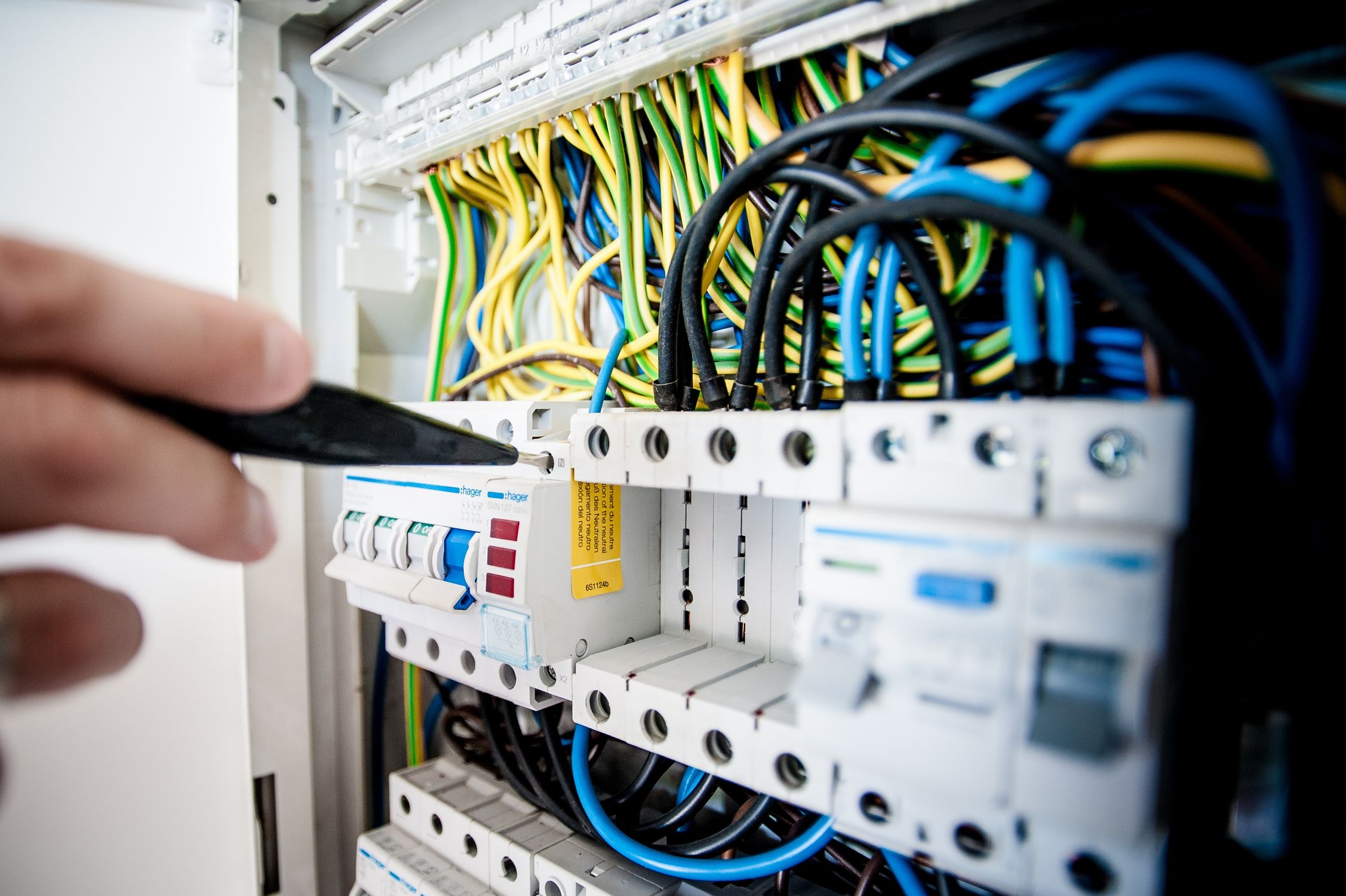
Switchgear is the protection and switching equipment between the transformer and the distribution panels. For mining facilities, key components include:
- Main breaker: The primary disconnect that can isolate the entire facility from the transformer. Must be rated for the full load current plus safety margin.
- Automatic Transfer Switch (ATS): If the facility has backup generation, the ATS automatically switches between utility and generator power during outages.
- Surge protection: Transient voltage surge suppressors (TVSS) at the main panel protect downstream equipment from utility-side voltage spikes. Essential for facilities in lightning-prone regions.
- Power factor correction: While ASIC PSUs have relatively high power factor (0.95+), large installations may benefit from capacitor banks to correct power factor to 0.98+, avoiding utility power factor penalties.
Power Distribution Architecture
The distribution system routes power from the main switchgear to individual mining racks. Common architectures include:
Panelboard Distribution
Traditional approach using electrical panelboards (breaker panels) with individual circuit breakers for each miner or group of miners. Simple and familiar to electricians, but becomes unwieldy above 500 miners due to the sheer number of circuits and panel space required.
Busway (Bus Duct) Distribution
Prefabricated busway systems run overhead or under-floor, with tap-off boxes that provide power connections at each rack position. Busway is more expensive per foot than cable but dramatically simplifies installation and reconfiguration at scale. Preferred for facilities above 1MW where rack layouts may change over time.
PDU (Power Distribution Unit) Architecture
Rack-mounted or floor-standing PDUs transform and distribute power to individual miners within a rack. Smart PDUs with per-outlet monitoring enable remote power cycling of individual miners and real-time power consumption tracking — essential data for cost allocation in multi-tenant hosting facilities.
Conductor Sizing and Voltage Drop
Undersized wiring creates voltage drop, which reduces miner efficiency and generates waste heat in the conductors. NEC (National Electrical Code) limits voltage drop to 3% for branch circuits and 5% total from service entrance to point of use. For mining facilities with long cable runs, this often means upsizing conductors one or two gauge sizes above the minimum ampacity requirement.
At 480V distribution (stepped down to 240V at the rack PDU), conductor sizes are smaller and voltage drop is less of an issue compared to 240V distribution throughout. This is why many large facilities use 480V primary distribution with step-down transformers at each row or pod.
Grounding and Bonding
Proper grounding protects equipment and personnel. Mining facilities require:
- Equipment grounding conductors from every rack and panel back to the main grounding bus
- Ground rods driven to appropriate depth for the soil type (typically 8-10 feet), with measured ground resistance below 25 ohms (below 5 ohms is ideal)
- Bonding of all metallic structures, raceways, and equipment enclosures to the grounding system
- Grounding verification annually with a ground resistance tester
What to Evaluate at a Hosting Facility
When touring a colocation hosting facility, evaluate the electrical infrastructure with these questions:
- What is the total transformer capacity, and what percentage is currently loaded?
- Is there N+1 transformer redundancy, or is a single transformer a single point of failure?
- Are the distribution panels rated for the actual load, with room for expansion?
- Is there per-circuit or per-PDU power monitoring for accurate billing?
- When was the last electrical inspection, and is the installation NEC-compliant?
- What is the facility’s SLA commitment on power availability?
Rax Mining’s data center facilities are engineered with properly sized transformers, three-phase distribution, and professional-grade switchgear across our Nebraska and Midwest locations. Schedule a consultation to discuss power infrastructure at your preferred hosting location.
Explore Rax Mining
- Bitcoin Miner Hosting — Competitive rates from $0.075/kWh
- NatGas MDU Units — 1MW modular datacenter containers
- Mining Profitability Calculator — Estimate your mining returns
- Our Facility — Tour our mining infrastructure