The Backbone Most Miners Overlook
Every conversation about Bitcoin mining profitability eventually comes down to power costs. But between the utility meter and the ASIC miner sits an entire electrical infrastructure that determines whether your operation runs safely, efficiently, and within code. Getting this infrastructure wrong does not just cost money in wasted energy — it creates fire hazards, triggers regulatory shutdowns, and can make your site uninsurable.
This guide covers the electrical systems that connect utility-scale power to mining-ready outlets: transformers, switchgear, distribution panels, grounding, and the process of interconnecting with your local utility.
Utility Interconnection: Where It All Starts
Talking to Your Utility
Before you sign a lease or pour concrete, engage with your electric utility. Mining operations need multi-megawatt service, and utilities do not simply flip a switch to deliver that kind of power. The interconnection process typically involves:
- Load letter or service request — a formal document specifying your power requirements, voltage, phase configuration, and expected ramp schedule
- System impact study — the utility analyzes whether the local grid can support your load without degrading service to other customers
- Infrastructure upgrades — if the existing grid cannot support your load, the utility may need to upgrade transformers, reconductor lines, or install new substations. You may be responsible for part or all of this cost.
- Interconnection agreement — a legal contract specifying delivery voltage, power factor requirements, demand limits, and rate structure
This process takes 3-18 months depending on the utility, location, and scale of your operation. Starting this conversation early is the single most important step in site development.
Service Voltage and Phase
Utilities deliver power at various voltages. Common configurations for mining operations:
- 480V 3-phase — standard for operations under 2 MW. Most ASIC power supplies accept 200-277V single-phase, derived from the 480V 3-phase supply via step-down transformers or autotransformers.
- 4,160V or 13,800V 3-phase — medium voltage service for operations above 2-3 MW. Requires customer-owned step-down transformers to reduce voltage for equipment use.
- 34.5 kV or 69 kV — high voltage service for very large operations (10+ MW). Requires a customer substation with primary metering.
Higher delivery voltage means lower current for the same power, which means smaller (cheaper) conductors and lower resistive losses. Operations above 5 MW almost always take service at medium or high voltage.
Transformer Sizing and Selection
Sizing the Transformer
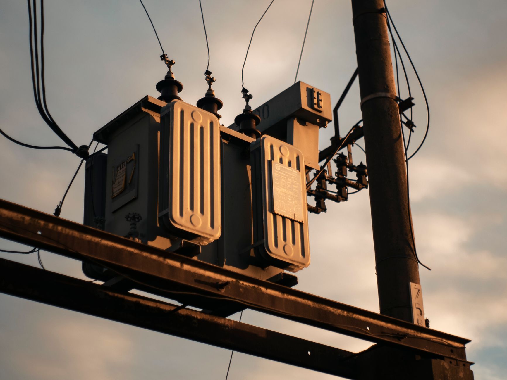
Transformers convert the utility’s delivery voltage to a voltage your equipment can use. Sizing requires knowing:
- Total connected load — sum of all ASIC miners, cooling systems, lighting, and ancillary equipment in kW
- Demand factor — mining operations run at nearly 100% load continuously, so your demand factor is close to 1.0 (unlike commercial buildings at 0.5-0.7)
- Power factor — ASIC power supplies typically operate at 0.95-0.99 power factor. Your utility agreement may require 0.90 or better, with penalties for reactive power consumption below that threshold.
- Future expansion — size your transformer for your planned capacity, not just your initial deployment. Replacing a transformer is expensive and disruptive.
The transformer rating in kVA should equal your total load in kW divided by your power factor, plus a 15-25% margin for safety and future growth. A 5 MW facility at 0.97 power factor needs approximately 5,155 kVA base, so a 6,000-6,500 kVA transformer provides appropriate headroom.
Transformer Types
- Pad-mount transformers — oil-filled, installed outdoors on a concrete pad. Most common for mining operations. Reliable, efficient, and available in standard sizes up to 10,000 kVA.
- Dry-type transformers — air-cooled, can be installed indoors. Lower fire risk but less efficient at high loads. Typically used for smaller step-down applications within the facility.
- Cast-resin transformers — encapsulated windings resist moisture and contamination. Higher cost but better for harsh environments (dust, humidity, chemical exposure).
Lead Times and Procurement
Post-2023, transformer lead times have extended dramatically. Pad-mount units in the 2,000-5,000 kVA range commonly have 26-52 week lead times. For large mining deployments, order transformers before finalizing other construction details. Used or refurbished transformers can be sourced faster but require careful inspection and testing.
Switchgear: The Control Center
What Switchgear Does
Switchgear is the assembly of circuit breakers, disconnect switches, fuses, and bus bars that controls, protects, and isolates electrical equipment. In a mining facility, switchgear serves three critical functions:
- Protection — circuit breakers trip to isolate faults before they damage equipment or cause fires
- Control — operators can energize or de-energize circuits for maintenance, expansion, or load management
- Metering — integrated current transformers and voltage transformers provide real-time monitoring of power consumption, power factor, and harmonic distortion
Medium Voltage vs Low Voltage
If you take service at medium voltage (4,160V or above), you need medium voltage switchgear upstream of your transformers. This equipment is significantly more expensive than low-voltage gear but is required by code for safe operation at these voltages.
Downstream of the transformers, low-voltage switchgear (480V) distributes power to your mining rows through panel boards and bus ducts.
Arc Flash Considerations
Mining facilities operate high-current electrical systems in enclosed spaces — a combination that creates serious arc flash hazards. An arc flash study (per NFPA 70E) is not optional. The study determines:
- The incident energy at each point in your electrical system
- The required Personal Protective Equipment (PPE) category for workers at each location
- The arc flash boundary — the minimum safe working distance for unprotected personnel
Label every panel, switchgear enclosure, and disconnect with its arc flash hazard information. This is a code requirement and an insurance requirement.
Power Distribution Within the Facility
From Switchgear to Miners
The path from your main switchgear to individual ASIC miners typically follows this hierarchy:
- Main switchgear (480V 3-phase) — feeds distribution panels or bus ducts
- Distribution panels or bus ducts — each serves a row or zone of miners
- Power Distribution Units (PDUs) — rack-level or row-level units that provide individual outlets for miners
- Power supply units (PSUs) — inside each ASIC miner, converting facility power to the DC voltages the hash boards need
Bus Duct vs Cable
For distributing power within the facility, you have two primary options:
- Bus duct (busway) — pre-engineered aluminum or copper bus bars enclosed in a protective housing. Tap boxes allow connections along the run. Fast to install, easy to reconfigure, excellent for mining rows that may be rearranged. More expensive per foot but lower labor cost.
- Cable and conduit — traditional wiring from panels to receptacles. Lower material cost but higher labor cost, and much harder to modify after installation.
Most operations above 2 MW favor bus duct for its flexibility and lower total installed cost at scale.
Conductor Sizing
Mining loads are continuous (running more than 3 hours without interruption), which means NEC Article 210.20 requires conductors to be rated at 125% of the continuous load. This is not optional — it is a code requirement that directly affects safety.
For example, if a circuit serves 30A of mining load, the conductor and overcurrent protection must be rated for at least 37.5A (round up to 40A). Undersizing conductors is the most common electrical code violation in mining facilities, and it is the leading cause of electrical fires.
Grounding and Bonding
Proper grounding is non-negotiable for mining operations. The combination of high power density, metallic enclosures, and continuous operation creates conditions where a grounding failure can be lethal.
Key Requirements
- Equipment grounding conductor — every metal enclosure, rack, and container must be bonded to the grounding system
- Grounding electrode system — ground rods, ground rings, or concrete-encased electrodes providing a low-impedance path to earth
- Bonding jumpers — connecting all metallic systems (electrical, plumbing, structural steel) to prevent voltage differences that could energize exposed metal
- Ground fault protection — required by NEC for services above 1,000A at 480V. Ground fault relays detect current flowing through unintended paths and trip the main breaker.
Container and Modular Deployments
Mining containers present unique grounding challenges. Each container is an isolated metal enclosure that must be bonded to the site grounding system. If containers are stacked or placed in rows, the bonding connections between containers and to the main ground grid must be designed to handle fault currents without creating voltage gradients across walkways.
Code Compliance: NEC, NFPA, and Local Amendments
Bitcoin mining facilities must comply with:
- National Electrical Code (NEC/NFPA 70) — the baseline for all electrical installations in the United States
- NFPA 70E — standard for electrical safety in the workplace (arc flash, lockout/tagout, PPE)
- NFPA 75 — standard for protection of IT equipment (applicable to mining as electronic computing equipment)
- Local building codes — many jurisdictions adopt NEC with amendments. Some have specific data center or high-density computing provisions.
- Utility interconnection standards — IEEE 1547 for distributed resources, or utility-specific standards
Engage a licensed electrical engineer familiar with data center or industrial power systems to design your electrical infrastructure. This is not a place for self-taught electrical work. Inspectors in most jurisdictions will require stamped engineering drawings before issuing permits.
Common Electrical Design Mistakes in Mining
Undersizing for Continuous Load
The most dangerous mistake. Mining loads are continuous by definition. Every conductor, breaker, and panel must be rated at 125% of the load. Operators who size for 100% are violating code and creating fire hazards.
Ignoring Harmonics
ASIC power supplies are switched-mode converters that inject harmonic currents into the electrical system. High harmonic distortion overheats neutral conductors (which carry the sum of triplen harmonics from all three phases), reduces transformer capacity, and can cause nuisance trips on breakers. Specify K-rated transformers and oversized neutral conductors for mining applications.
Skipping the Utility Conversation
Operators who build their facility before confirming utility capacity often discover that the local grid cannot deliver their required power. The resulting upgrade costs and delays can be devastating. Always start with the utility.
Poor Voltage Drop Management
Long cable runs from panels to miners create voltage drop that reduces miner efficiency and can cause hash board errors. NEC recommends maximum 3% voltage drop for branch circuits and 5% total. At the power densities common in mining, even modest cable lengths can exceed these limits. Use larger conductors or locate distribution panels close to the load.
No Spare Capacity
Building your electrical system to exactly match your current load leaves no room for growth, equipment replacements, or higher-efficiency miners that draw more power. Design for at least 125% of your planned maximum deployment.
Monitoring and Maintenance
Once your electrical infrastructure is operational, ongoing monitoring prevents small problems from becoming catastrophic failures:
- Power monitoring — install meters at each major distribution point to track consumption, power factor, and voltage by zone
- Thermal imaging — quarterly infrared scans of switchgear, panels, bus duct connections, and transformer terminals identify hot spots from loose connections or overloaded circuits
- Transformer oil analysis — for oil-filled transformers, annual dissolved gas analysis (DGA) detects internal arcing, overheating, or insulation degradation before they cause failures
- Breaker testing — periodic testing confirms that circuit breakers will actually trip at their rated settings. Breakers that have never operated under fault conditions may fail when needed.
Planning Your Electrical Build
The sequence for a successful mining electrical deployment:
- Contact your utility and submit a service request (Month 1)
- Hire a licensed electrical engineer to design the system (Month 1-2)
- Order transformers and switchgear — long lead items (Month 2)
- Complete utility interconnection study and agreement (Month 3-6)
- Pull building and electrical permits (Month 4-6)
- Install site electrical infrastructure while waiting for equipment delivery
- Set and connect transformers and switchgear (Month 8-12)
- Commission, test, and inspect (Month 12-14)
- Energize and begin phased miner deployment
For operations working with Rax Mining hosting, the electrical infrastructure is already built, permitted, and operational. This eliminates 12-18 months of lead time and the capital expenditure of building your own substation.
If you are evaluating a self-hosted deployment, our consulting team can help you navigate the electrical engineering, utility negotiation, and procurement process. Reach out to start the conversation before you start the build.
Explore Rax Mining
- Bitcoin Miner Hosting — Competitive rates from $0.075/kWh
- NatGas MDU Units — 1MW modular datacenter containers
- Mining Profitability Calculator — Estimate your mining returns
- Our Facility — Tour our mining infrastructure