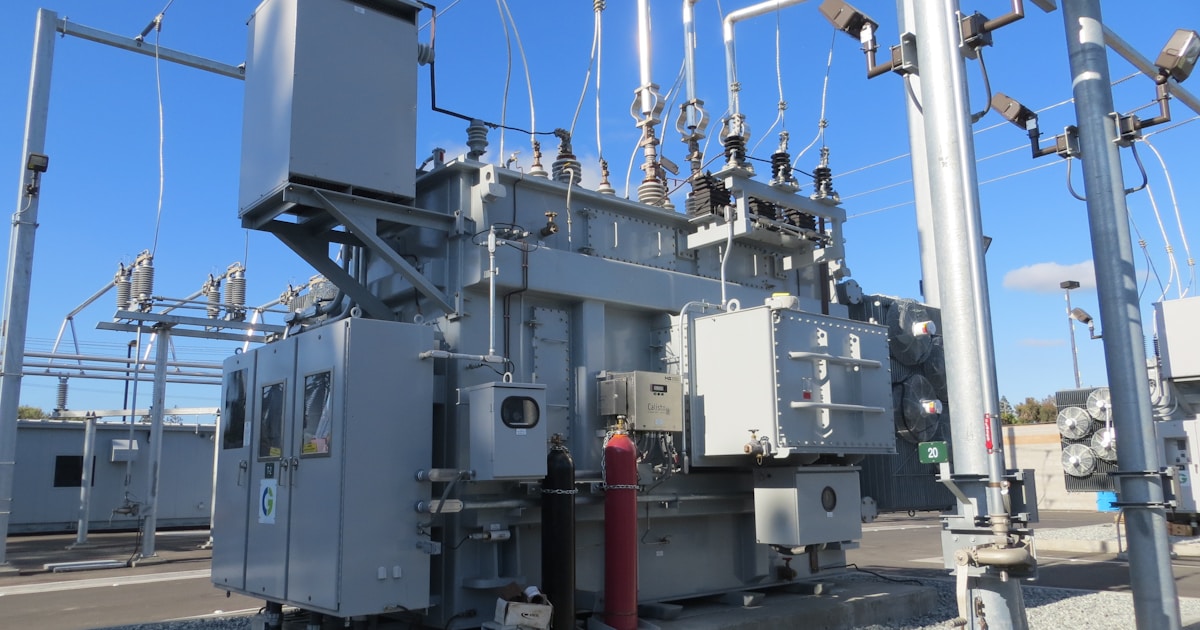
The electrical infrastructure behind a Bitcoin mining facility is its most expensive and least forgiving component. A single transformer sizing error, an undersized busbar, or an improperly rated breaker panel can shut down a multi-megawatt operation for weeks while replacement equipment ships. At current Bitcoin prices above $64,000, every day of downtime on a 10 MW facility costs roughly $12,000-18,000 in lost mining revenue.
This guide covers the electrical design decisions that matter most for mining operations from 1 MW to 30 MW — transformer selection, medium-voltage switchgear, low-voltage power distribution, and the redundancy strategies that keep miners hashing through equipment failures.
Understanding Mining Power Requirements
Bitcoin mining loads have unique electrical characteristics that differentiate them from traditional data center or industrial loads:
- Near-unity power factor — ASIC miners use switching power supplies (PSUs) with power factor correction (PFC) circuits, typically achieving 0.95-0.99 power factor. This simplifies transformer sizing compared to motor-heavy industrial loads.
- Constant load profile — Mining runs 24/7 at near-constant draw. There are no demand spikes, no daily cycling. The load is essentially flat once miners are powered on.
- High density — A single Antminer S21 Pro draws 3,510W. A standard 40-ft shipping container can hold 250+ units, concentrating 875+ kW in 320 square feet. Power density per square foot far exceeds typical commercial buildings.
- Tolerance for brief interruptions — Unlike financial trading systems, mining can tolerate sub-second power interruptions. ASICs reboot and rejoin pools within 2-5 minutes after a power blip, making automatic transfer switches (ATS) between utility feeds practical without UPS infrastructure.
Utility Service and Transformer Sizing
Service Voltage Tiers
| Facility Size | Typical Service Voltage | Transformer Type | Lead Time |
|---|---|---|---|
| Under 500 kW | 480V 3-phase (from utility pad-mount) | Utility-owned pad-mount | 2-6 months |
| 500 kW – 5 MW | 12.47 kV or 13.8 kV primary to 480V secondary | Customer-owned pad-mount or unit substation | 4-12 months |
| 5 MW – 30 MW | 34.5 kV or 69 kV primary to 480V secondary | Customer-owned substation with multiple transformers | 8-18 months |
| 30 MW+ | 115 kV+ transmission-level | Full HV substation with utility co-investment | 12-36 months |
Critical planning note: Transformer lead times are the longest single item in mining facility construction. In the current market, large power transformers (5+ MVA) often have 12-18 month delivery windows. Order transformers before finalizing the building design — not after.
Transformer Sizing Formula
For mining loads with high power factor:
Required kVA = Total kW load / Power Factor / Derating Factor
Example for a 5 MW facility:
- Total IT load: 5,000 kW
- Cooling and auxiliary: 250 kW (5% overhead for fans, lighting, monitoring)
- Total load: 5,250 kW
- Power factor: 0.97
- Derating factor: 0.80 (run transformers at 80% to manage heat and extend life)
- Required transformer: 5,250 / 0.97 / 0.80 = 6,762 kVA
- Select: 7,500 kVA transformer (next standard size up)
Running transformers above 80% continuous loading accelerates insulation aging. Oil-filled transformers have temperature-dependent lifespans — every 6C above rated hot-spot temperature halves insulation life. For 24/7 mining loads, the 80% derating rule is not conservative; it is essential for a 20-25 year transformer life expectancy.
Transformer Cooling Types
| Type | Cooling | Cost (per MVA) | Best For |
|---|---|---|---|
| ONAN (Oil Natural, Air Natural) | Passive oil + radiators | $20,000-35,000 | Under 5 MVA, temperate climates |
| ONAF (Oil Natural, Air Forced) | Oil + fan-cooled radiators | $25,000-40,000 | 5-15 MVA, most mining facilities |
| OFAF (Oil Forced, Air Forced) | Pumped oil + fans | $35,000-50,000 | 15+ MVA, hot climates, tight spaces |
| Dry-type (cast resin) | Air cooled, no oil | $40,000-60,000 | Indoor, fire-sensitive, smaller sizes |
Medium-Voltage Switchgear
Facilities receiving power above 600V require medium-voltage (MV) switchgear between the utility service point and the step-down transformers. For mining operations at 5 MW and above, this is typically a metal-clad switchgear lineup rated at 15 kV or 38 kV class.
Key Specifications
- Interrupting capacity — Must exceed the available fault current at the service point. Utility will provide a fault current study; typical values range from 10 kA to 40 kA depending on proximity to the utility substation.
- Bus rating — Continuous current rating of the main bus. Size for at least 125% of maximum expected load to accommodate future expansion.
- Protection relaying — Microprocessor-based protective relays (SEL, GE Multilin, or equivalent) for overcurrent, ground fault, and under/over voltage protection. Mining loads are simple from a protection standpoint, but proper relay coordination with the utility is mandatory.
- Metering — Revenue-grade metering at the service point, plus facility-side metering for operational monitoring. Most power purchase agreements (PPAs) reference the revenue meter for billing.
Low-Voltage Power Distribution
From the transformer secondary (typically 480V 3-phase) to the individual ASIC miners, the distribution architecture must balance cost, flexibility, and maintainability.
Architecture Options
| Architecture | Description | Cost | Best For |
|---|---|---|---|
| Centralized switchboard + cable runs | Single main switchboard feeds panelboards via cable/conduit | Lowest | Under 1 MW, simple layouts |
| Busway (busduct) | Rigid enclosed bus bars with plug-in tap boxes | Moderate | 1-10 MW, row-based layouts |
| Remote power panels (RPPs) | Factory-built panels distributed through the facility | Moderate-High | 5-30 MW, containerized or modular |
| PDU (Power Distribution Unit) | Integrated transformer + distribution in one cabinet | Highest | Data center conversions, precision loads |
Busway: The Mining Facility Standard
For facilities from 1-10 MW, busway (also called busduct) has become the de facto standard for mining power distribution. A typical layout runs a 2,000-4,000 amp copper busway overhead down each row of miners, with plug-in tap boxes every 3-4 feet feeding individual ASICs or small groups.
Advantages for mining:
- Rapid deployment — Busway installs in hours per section versus days for cable/conduit runs.
- Flexibility — Tap boxes can be relocated along the busway as rack layouts change.
- Reduced copper — A single busway replaces dozens of parallel cable runs, reducing total copper weight by 30-50%.
- Maintainability — Individual tap boxes can be isolated and replaced without de-energizing the entire bus.
Circuit Sizing for ASIC Miners
NEC Article 210 and 220 govern branch circuit sizing. For ASIC miners treated as continuous loads (operating more than 3 hours), circuits must be rated at 125% of the connected load:
Example for a row of 10 Antminer S21 Pro units (3,510W each at 240V single-phase):
- Total load: 35,100W / 240V = 146.25A
- Continuous derating: 146.25 x 1.25 = 182.8A
- Required: 200A circuit with appropriate conductor sizing per NEC Table 310.16
Most mining facilities use 20A or 30A branch circuits feeding 1-2 ASICs per circuit, aggregated through tap boxes on the busway. This allows individual miner isolation without affecting the row.
Grounding and Bonding
Proper grounding protects both personnel and equipment. Mining facilities must comply with NEC Article 250, with particular attention to:
- Equipment grounding conductors sized per NEC Table 250.122 for each branch circuit.
- Grounding electrode system — Ground rods, concrete-encased electrodes (Ufer grounds), or ground rings. Soil resistivity testing determines the electrode configuration needed to achieve the target ground resistance (typically under 5 ohms, ideally under 1 ohm).
- Bonding of all metallic components — Racks, busway, conduit, building steel. A single ground fault path must have sufficiently low impedance to trip the overcurrent device quickly.
- Surge protection — Type 1 SPD at the service entrance, Type 2 at distribution panels. Lightning-prone areas may require enhanced protection with dedicated lightning rods and down conductors.
Redundancy Strategies by Facility Tier
| Tier | Redundancy | Expected Availability | Capital Premium | Mining Application |
|---|---|---|---|---|
| Basic | Single utility feed, single transformer | 99.0-99.5% | Baseline | Owner-operated, cost-sensitive |
| Standard | Dual utility feeds (A/B) with ATS, single transformer | 99.5-99.9% | +15-25% | Most hosting facilities |
| Enhanced | Dual feeds, N+1 transformers, redundant switchgear bus | 99.9-99.95% | +40-60% | Premium hosting, SLA-bound |
| Data Center | 2N fully redundant (concurrent maintainable) | 99.99%+ | +80-120% | Overkill for mining ROI |
Most mining operations target Standard tier — dual utility feeds with automatic transfer provide meaningful uptime improvement without the capital cost of full N+1 transformer redundancy. The “Enhanced” tier is justified only when hosting contracts include uptime SLAs with financial penalties.
Common Electrical Design Mistakes in Mining
- Undersizing transformers for continuous duty — Nameplate rating assumes 30C ambient and intermittent loading. Mining loads are continuous at potentially higher ambient temperatures. Without derating, transformer hot-spot temperatures exceed design limits and insulation degrades rapidly.
- Ignoring harmonic distortion — ASIC power supplies generate harmonic currents (primarily 3rd, 5th, 7th). At scale, harmonics can overheat neutral conductors, cause transformer derating, and trip sensitive protection relays. A power quality study and K-rated transformers or harmonic filters may be required for facilities above 5 MW.
- Insufficient conductor sizing for voltage drop — Long cable runs from transformer to load center can exceed the NEC 3% voltage drop recommendation. Low voltage at the ASIC PSU input reduces efficiency and can cause PSU fault conditions. Keep cable runs short or upsize conductors.
- No metering at the row level — Without per-row or per-circuit metering, operators cannot identify energy waste, failed ASICs drawing power but not hashing, or circuit imbalance. Smart PDUs or metered tap boxes add $50-100 per circuit but enable data-driven operations.
- Ordering transformers last — The most common project delay. Transformer lead times are 6-18 months. Breaking ground before securing a transformer delivery date is a project management failure.
Rax Mining: Purpose-Built Electrical Infrastructure
Rax Mining’s hosting facilities are engineered with properly sized transformers, busway distribution, and environmental controls designed specifically for high-density ASIC mining. Our NatGas MDU deployments include integrated power generation and distribution, eliminating the lead time and cost of utility interconnection for off-grid sites. Visit our shop for turnkey ASIC packages with hosting, or schedule a consultation to discuss custom power infrastructure for your mining operation.
Frequently Asked Questions
What size transformer do I need for a 5 MW Bitcoin mining facility?
A 5 MW mining facility with 5% auxiliary overhead needs approximately 5,250 kW of total capacity. After accounting for power factor (0.97) and the recommended 80% continuous derating, you need a 6,762 kVA transformer — meaning a standard 7,500 kVA unit is the right selection. Always derate to 80% for 24/7 mining loads to protect transformer insulation life.
How long does it take to get a power transformer for a mining facility?
Lead times vary dramatically by size. Utility-owned pad-mount transformers (under 2 MVA) typically take 2-6 months. Customer-owned transformers in the 5-15 MVA range currently have 8-18 month lead times. Large power transformers above 20 MVA can take 12-36 months. Order your transformer before finalizing building design.
Should I use busway or cable runs for power distribution?
For facilities from 1-10 MW, busway (busduct) is the standard choice. It installs faster, uses 30-50% less copper than parallel cable runs, and allows flexible tap-box placement for changing rack layouts. Cable runs are more economical only for very small facilities under 500 kW or when existing infrastructure already includes conduit paths.
Do Bitcoin miners cause harmonic problems on the electrical system?
Yes, at scale. ASIC power supplies generate harmonic currents (primarily 3rd, 5th, and 7th harmonics) that can overheat neutral conductors and transformers. Facilities above 5 MW should conduct a power quality study and may need K-rated transformers or active harmonic filters. Below 5 MW, standard transformers with appropriate derating usually handle the harmonic content adequately.
What level of electrical redundancy is appropriate for a mining facility?
Most mining operations target dual utility feeds with automatic transfer switch (ATS), providing 99.5-99.9% availability at a 15-25% cost premium over single-feed designs. Full N+1 transformer redundancy is justified only when hosting contracts include financial penalties for downtime. Data-center-grade 2N redundancy is rarely cost-effective for mining economics.
Explore Rax Mining
- Bitcoin Miner Hosting — Competitive rates from $0.075/kWh
- NatGas MDU Units — 1MW modular datacenter containers
- Mining Profitability Calculator — Estimate your mining returns
- Our Facility — Tour our mining infrastructure